Title here
Summary here
February 8, 2012 in Systems5 minutes
Port-Channels, are a way of aggregating physical links together so that you can load balance traffic over each link to increase bandwidth, and create more redundancy. You might commonly see this configured between two switches, as shown below:
Each link works together to form a logical, loop-free interface. These are relatively commonplace, and in this scenario highly useful because it prohibits spanning tree from blocking one of these ports, allowing the switch to utilize each link.
What if, instead of one Catalyst 6500, you had two? My previous post on VSS covered this in some detail. You are able to group two switches together to form a single logical switch. This means you can establish a port channel to both switches just like it was a single switch. Concepts such as VSS fall under a description that Cisco refers to as “Multi-chassis EtherChannel”, or MEC.
NX-OS brings a new feature to the MEC family, called Virtual Port Channels. However, there are a few key differences. VPC doesn’t form a “virtual switch” like the 6500 does, in that it keeps the control plane independent on each switch. Port channels can still be established between an end device and both Nexus switches, because vPC works together with LACP to ensure that the end device has a consistent path through the network. The VPC utilizes a highly available link between them, known as a peer-link. Typically this should also be a port channel for increased redundancy.
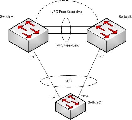
The peer link is typically multiple port-channeled links between the switches that is used to synchronize state between the two switches. It is also used for forwarding multicast and broadcast traffic. It will also forward unicast traffic in the event of a failure. Because of this, it should be configured as a trunk, passing all VLANs you wish to pass in that scenario. It’ typically high-bandwidth and highly available, so that it can be used to forward traffic reliably in a failover condition - thus, it’s commonly seen as a port channel between the switches. It’s a good idea to compose this port channel of at least 2x 10G interfaces on separate linecards. It’s also important to understand how your spanning tree design will impact this link in a failure. The peer link will not do you any good if spanning tree places it into a blocking state
In order for VPC to be an appropriate redundancy mechanism, it does implement some additional features. The ARP and MAC address tables are synched between the two switches so that in the event that a Nexus goes down, there’s no learning period for the remaining switch - it can begin forwarding frames immediately.
Another important component is the heartbeat link. This sends pings back and forth between the switches so that if the peer link were to fail for whatever reason, a split-brain would not occur. This can be just about any sort of connection between the two switches, even from the “mgmt0” interface. Just about any network would do as long as it’s reasonably reliable. Some have used actual 10G ports on the back of the switch for this heartbeat because they feel like they need to make the connection that much more reliable. I don’t typically advise that method, since those ports are usually heinously expensive. The heartbeat link should also be made a routed link (i.e. “no switchport”) as opposed to an SVI. vPC will show issues with SVIs in some cases, and could cause a “chicken and egg” situation in which the heartbeat SVI will not come up at all, preventing vPC from converging properly.
Once you have the physical cabling set up, vpc is actually remarkably easy to configure:
vpc domain 1
   role priority 1000
   peer-keepalive destination 192.168.1.2 source 192.168.1.1 vrf vpc_keepalive
   delay restore 40
   peer-gateway
This configures the vPC-specific features. The role priority number controls which switch becomes the primary peer device.
The “peer-keepalive” command specifies where heartbeats should be sent. Note that the VRF context is also specified - having the heartbeat on a separate VRF is a best practice, and that’s why “vpc_keepalive” exists by default as it’s own VRF.
The “delay restore” command configures how long vPC waits to come up after the device has been reloaded. This gives routing protocols and the FIB table a chance to converge. The default is 30 seconds - tweak as your design requires.
The “peer-gateway” command is useful in conjunction with something like HSRP. Some vendors (cough, cough EMC - and others) have decided they know best on what MAC addresses they need to be sending to. They ignore the ARP messages sent out by a pair of HSRP-enabled devices, and send to the MAC address they received from. The “peer-gateway” command allows the correct vPC peer to act as the gateway, all without the need to cross the peer-link.
Finally, to configure the vPC ports, simply set them up in a port-channel, except that each member of the port channel will be on different switches. In the port channel interface (i.e. po2), type the following to make that port channel a member of the vPC domain:
switch(config-if)# vpc 1
Keep in mind that vPC is a layer 2 technology and there are some important things to consider when designing a solution where routing protocols travel across a vPC. (See this post for a good discussion on what you should be aware of in such a design.)
Credit: Virtual PortChannels: Building Networks without Spanning Tree Protocol - Cisco http://www.cisco.com/en/US/prod/collateral/switches/ps9441/ps9402/white_paper_c11-516396.html Images from Cisco.com