Title here
Summary here
November 13, 2012 in Systems15 minutes
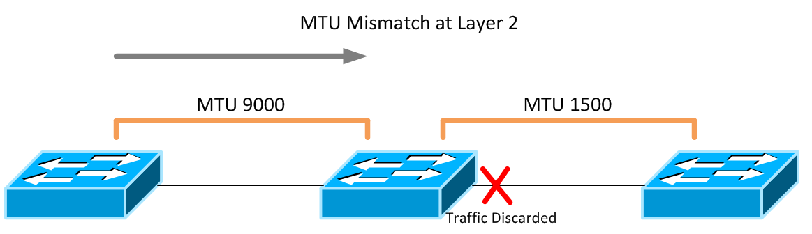
When you’re talking about something like MTU or QoS, it’s important to think about technology implementations in an end-to-end fashion by analyzing every possible path network traffic can take - always planning for the big picture and never simply a single connection between devices. For instance, poor planning can result in confusing QoS configurations that don’t match from device to device. Depending on the platform, this can result in mismatched MTU configurations, which at worst breaks your network and at best causes elusive performance problems that can be incredibly difficult to troubleshoot. A layer 2 domain that has an incorrect MTU configuration will simply discard frames as they encounter a boundary with a lower MTU than their size.
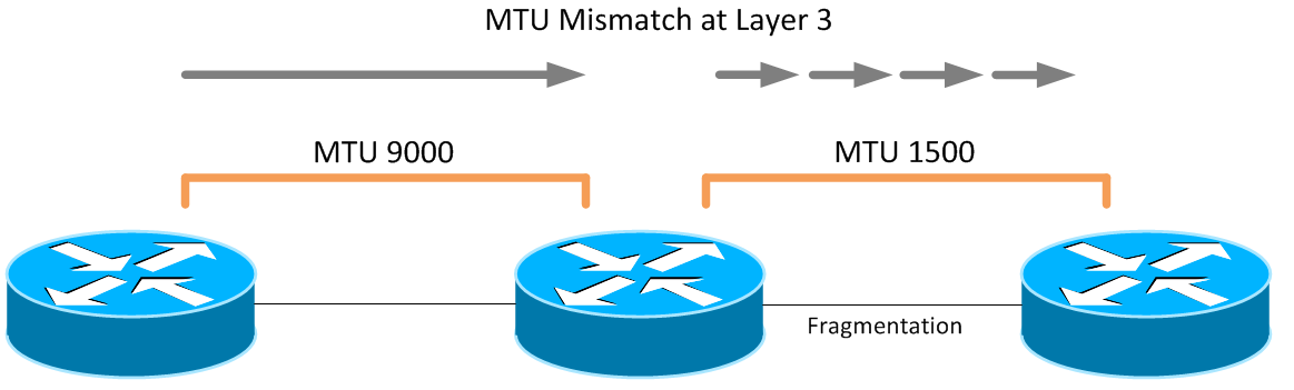
Layer 3 topologies with MTU bottlenecks are able to overcome this, but only by breaking each packet down into fragments that can be sent through the link with the lower MTU. Though this allows packets to be transmitted and not simply dropped, it does place additional load on the router, which is responsible for carving up each large packet into acceptable sizes.
Both scenarios can produce extremely strange symptoms. For instance, some file transfer protocols such as NFS will work to a degree, even in the event of a Layer 2 MTU mismatch, because certain packets required for controlling the connection for an NFS session are not that large, and won’t be dropped. However, once files start moving, the packet size increases and will then grow larger than the MTU of a given link. This scenario, if you’re not looking for MTU, can be extremely difficult to troubleshoot.
Cisco’s new QoS architecture (MQC) can be used to configure MTU size for certain types of traffic as well as a slew of other traffic management features. QoS and MTU can be configured on Cisco UCS, Cisco Nexus, and VMware ESXi in a way that they work together, but it can be a confusing process. Imagine that you find these technologies in a pod-like design and QoS must be configured similarly from end-to-end. With UCS, inter-blade traffic that is pinned to the same fabric interconnect can be done internally, meaning the only configuration that you need to worry about is within UCS. However, sometimes traffic needs to go from A to B, and as a result will utilize the upstream switch, in this scenario, a Cisco Nexus 5K.
There’s a reason this section is first. The push towards Modular QoS CLI (MQC)is evident in nearly every new Cisco device, especially those in the Nexus line. Even many seasoned Route/Switch veterans are confused because MQC is very different from the way QoS used to be done. I typically choose to do this first because it can be the most complex, and it allows me to define what my markings are, etc. I then match the configuration on all the other devices. There are three distinct components of a QoS configuration in the context of MQC:
Class Maps - these separate traffic into various classes. Typically I’ve seen these separated by priority, so that we can refer to top-priority traffic as something like “Platinum Traffic”, but I’ve also heard that some like to name the class-maps according to the main protocol those classes are intended to carry, such as VoIP. They don’t really “do” anything with the traffic other than classify it logically within the switch.
Policy Maps - these allow the device to make changes with the way traffic is handled. Things like MTU changes, prioritization, bandwidth reservations, etc. are all handled here. Policy maps, in effect, “do stuff”. In order to “do stuff” though, policy maps always have to refer to class-maps so that different types of traffic can be handled differently.
Application - If policy maps refer to class maps, then what refer to policy maps? The answer is - it depends. Policy maps are what “do stuff”, so you need to apply them to something, much like an access list or route map. You can apply a policy map globally, or on a per-interface basis, if you want different interfaces to perform QoS differently. This article will be using the former.
First, let’s identify our traffic. I separate traffic types into classes, but you can name these whatever you want. Just remember what marking you’re using for what classes because you’ll want to keep it consistent throughout to make it easier on yourself. I use CoS for identification, but you can use any number of classification mechanisms, including DSCP, access lists, etc.
class-map type qos match-all class-platinum
  match cos 5
class-map type qos match-all class-gold
  match cos 4
class-map type qos class-fcoe
  match cos 3
class-map type qos match-all class-silver
  match cos 2
class-map type qos match-all class-bronze
  match cos 1
The class “class-fcoe” is a default class, and unless otherwise specified, uses a CoS value of 3 by default. I’m keeping this default, and using other CoS values for the other traffic classes. All of these class-maps are of type “qos”, which if you recall from part 1 in this series, are used for traffic identification. So now that I have my class maps, I need to create a policy map that takes the traffic that has been classified into something that the internal queuing logic of the switch can understand. Cisco uses QoS groups for this. Note that there is no correlation between CoS and QoS groups. This is where you have to plan out what numbers you want to use for each and keep track of where things flow internal to the switch. QoS groups are just a way of keeping track of this traffic between the different types of QoS policies.
policy-map type qos system-level-qos
  class class-platinum
    set qos-group 5
  class class-gold
    set qos-group 4
  class class-silver
    set qos-group 3
  class class-bronze
    set qos-group 2
  class class-fcoe
    set qos-group 1
Remember how I said there’s no correlation between CoS and QoS groups? See how I’m using QoS group 3 for my Bronze traffic, and there is no QoS group 1 shown here? In the network class maps, I noted that FCoE by default uses the CoS marking of 3. Well, it also uses a default QoS group of 1. In fact, if you try to change what QoS group FCoE gets sent to, FCoE will not work. I brought down an entire SAN before I found this out - just leave FCoE at it’s default. Next, we can create new class-maps of type “queuing” that matches against traffic that we placed in these QoS groups in the policy map I just showed:
class-map type queuing class-platinum
  match qos-group 5
class-map type queuing class-gold
  match qos-group 4
class-map type queuing class-silver
  match qos-group 3
class-map type queuing class-bronze
  match qos-group 2
class-map type queuing class-fcoe
  match qos-group 1
Now that I’ve created a list of class maps that are of type “queuing”, I can do cool stuff like bandwidth reservation, as well as giving priority to a certain queue:
policy-map type queuing Uplink-out_policy
  class type queuing class-platinum
    bandwidth percent 10
    priority
  class type queuing class-gold
    bandwidth percent 20
  class type queuing class-silver
    bandwidth percent 20
  class type queuing class-bronze
    bandwidth percent 10
  class type queuing class-fcoe
    bandwidth percent 30
  class type queuing class-default
    bandwidth percent 10
Note that if I want to do other stuff like MTU changes, or apply pause or congestion control behaviors, you need to use the other type of policy: “Network QoS”. Because of this, we need a new set of class-maps to grab the traffic that’s already been assigned a QoS Group and allow it to be used by a Network QoS policy map.
class-map type network-qos class-platinum
  match qos-group 5
class-map type network-qos class-gold
  match qos-group 4
class-map type network-qos class-silver
  match qos-group 3
class-map type network-qos class-bronze
  match qos-group 2
class-map type network-qos class-fcoe
  match qos-group 1
This appears virtually identical to the last group of class-maps since we’re still matching on the qos-groups we assigned earlier, but this time we’re using a different type of class-map (“network-qos”) so we can apply to a different type of policy map. Speaking of which, we can now create our “network-qos” policy map:
policy-map type network-qos system-level-net-qos
  class type network-qos class-platinum
    set cos 5
  class type network-qos class-gold
    set cos 4
  class type network-qos class-fcoe
    pause no-drop
    mtu 2158
    set cos 3
  class type network-qos class-silver
    set cos 2
    mtu 9126
  class type network-qos class-bronze
    set cos 1
  class type network-qos class-default
    multicast-optimize
There are a few very important points I’d like to make regarding the above policy-map, which I view as one of the most important components of this entire configuration.
The class “class-default” isn’t a class I created, but one native to the switch. This class allows you to do things to traffic that doesn’t make it into any other class. Think of it as the “everything else” class. This does not have an MTU statement, meaning it gets the Ethernet default MTU, which is 1500 bytes. I also applied jumbo frames to class silver, where I’m running a few applications that require it. All other traffic either gets 1500, or in the case of FCoE, 2158. This
We’re re-tagging traffic with a CoS value, which if you follow the flow of this configuration is the same CoS value each class had when it came in. We do this so adjacent devices can have similar configurations without having to interpolate between CoS values.
You must, and I repeat again, you must include the fcoe class in this policy-map (with the values I provided as a best practice unless you need to change it), otherwise FCoE will not work. This was another reason I ran into issues because I didn’t realize that FCoE actually needs to be called out in this policy map, even though the class “class-fcoe” is a native class on the switch.
The remaining task is to apply these policies to either a specific set of interfaces, or globally to all interfaces. This depends on the type of policy being used. Policies of type “network-qos” can only be applied globally. Policies of type “qos” can be applied globally or to any interface, but only applies to input traffic. Finally, policies of type “queuing” are what really provides the most “QoS-like” features like queue scheduling and bandwidth shaping; these can be applied globally, or per-interface, and can apply to both input and output traffic.
For simplicity, we will be applying all of these policies globally, under the “system qos” context:
system qos
 service-policy type queuing input fcoe-default-in-policy
 service-policy type queuing output Uplink-out_policy
 service-policy type qos input system-level-qos
 service-policy type network-qos system-level-net-qos
Note that I also used a native service policy for input traffic at the top called “fcoe-default-in-policy” - I like to use this for at least ingress traffic so that I can just get FCoE working with minimal effort. Your mileage my vary, and FCoE may not be a concern for you.
That’s it! The class-map connects to the policy-map which connects to the system qos context, which connects to the hip bone and…. Anyways, as an addition, there are also two other classes you can use besides “class-default” and “class-fcoe” that I’d like to point out. These are native to the switch and you can use them in your “worker” policy map to affect the listed traffic. These descriptions are from Cisco’s N5K QoS Configuration Guide:
class-all-flood - The class-all-flood class map matches all broadcast, multicast, and unknown unicast traffic (across all CoS values). If you configure a policy map with the class-all-flood class map, the system automatically uses all available multicast queues for this traffic.
class-ip-multicast - The class-ip-multicast class map matches all IP multicast traffic. Policy options configured in this class map apply to traffic across all Ethernet CoS values. For example, if you enable optimized multicast for this class, the IP multicast traffic for all CoS values is optimized.
The VMware side of things is relatively simple. When using Cisco UCS B-Series blades, a common practice (and my recommendation) is to configure a separate vSwitch with it’s own vmkernel port dedicated to a singular purpose, since it’s fairly easy to simply add additional virtual NICs. In ESXi, you might want to enable jumbo frames - and some kind of QoS priority - to NFS traffic for your vSphere datastores to increase performance - especially in order to best take advantage of 10GbE, which a lot of datacenters are at or moving towards. Assuming the connectivity is already configured at defaults, the MTU for all connections is 1500. So, we will need to set the MTU of not only the vmkernel port for which we would like to enable jumbo frames, but also the entire vSwitch where that vmkernel resides. The configuration for changing from defaults to jumbo frames is threefold:
This has been truncated down quite a bit to fit on the page, but all the relevant details are there.
~ # esxcfg-vmknic -l
 Interface Port Group IP Address   Netmask          MTU
 vmk0      Mgmt       10.45.64.77  255.255.255.192  1500
 vmk1      NFS        192.168.2.21 255.255.255.0    1500
As you can see, there are two vmkernel ports on this vSwitch. One is used for management, and the other for NFS connectivity. First, lets delete and recreate the vmkernel port with the MTU set to 9000:
~ # esxcfg-vmknic -d NFS
~ # esxcfg-vmknic -a -i 192.168.2.21 -n 255.255.255.0 -m 9000 NFS
Next, we have to enable jumbo frames on the entire vSwitch. This won’t affect other vmkernel ports, just allows jumbo frames from vmkernel ports that already have it configured, very similar to the way a physical switch works. We don’t have to delete the vSwitch to make this configuration change, it can be done live.
~ # esxcfg-vswitch -m 9000 vSwitch1
Another look at the vmkernel port list and the vSwitch list shows that our configuration was successful.
~ # esxcfg-vmknic -l
 Interface Port Group IP Address   Netmask          MTU
 vmk0      Mgmt       10.45.64.77  255.255.255.192  1500
 vmk1      NFS        192.168.2.21 255.255.255.0    9000
~ # esxcfg-vswitch -l
Switch Name    MTU     Uplinks
vSwitch0       1500    vmnic0,vmnic1
vSwitch1       9000    vmnic2,vmnic3
The command “esxcfg-vmknic -l” allows you to view the configuration of the vmkernel ports currently in use on the host. Notice that the second output of this command shows that we’ve successfully set the MTU appropriately, as does the command “esxcfg-vswitch -l”, shown at the end.
You can use a VDS like the 1000v to do cool stuff like CoS marking from your VM port groups, but I’m going to write out this section assuming you don’t have that, and therefore have to use UCS to mark traffic. There will be another article concerning QoS when a VDS is being used. Traffic classification in UCS is done on a per-vNIC basis. If you want a certain type of traffic to be treated a certain way, it needs it’s own vNIC(s). This is because each vNIC (or vNIC template) can be configured with it’s own QoS policy, which binds it to a particular traffic classification. Under the vNIC or vNIC template, you can configure both the MTU of the vNIC, as well as the QoS policy you wish to enforce on it:
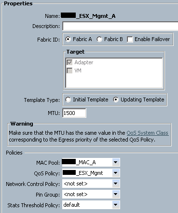
This means that all traffic leaving this vNIC will get the QoS Policy for ESX_Mgmt applied to it. So, we look at that QoS policy:
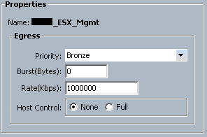
We see that all vNICs that are given this QoS policy are given a “Bronze” class of service. You can also configure bandwidth rates here. Finally, “host control” is a feature that allows the device connected to the vNIC to sent out CoS-tagged frames. This is useful if you’re using the Nexus 1000v, because that can do native CoS tagging per-portgroup. QoS in a virtual environment like this will be covered in another article. We aren’t using that for this purpose, so we want to turn this feature to “none”. Since this traffic is given a priority of “Bronze”, we need to go to the “QoS System Class” configuration page to see what that class of traffic is configured to do:
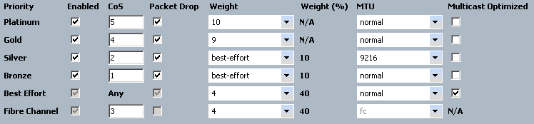
Since this vNIC is configured to send all traffic out with a “Bronze” class, and this class is configured to tag frames with a CoS value of 1, this means that the upstream switch will be able to classify traffic according to it’s policies. If you look back at our Nexus configuration, we have accordingly configured traffic with CoS 1 to be sent to it’s internal Bronze queue as well. In this way, the UCS and Nexus devices have been configured to work together with respect to QoS. MTU is important here as well. Let’s say that I want NFS traffic to get jumbo frames. I simply go to the vNIC template for that connectivity, give it a QoS policy that classifies that traffic into the “Silver” queue, and all NFS traffic will exit UCS with CoS value 2 and MTU of 9216. Different types of traffic simply require a different class of service. This “QoS System Classes” page is where you want to make sure that your configuration matches that of the upstream switch.
There are so many rabbit holes I could go down with this stuff but I just wanted to do a brief overview of how multiple systems can be configured together in a datacenter with respect to QoS. This article is already huge, so I’m going to stop. Candidly speaking, this one is several months in the making, as I’ve set this article down many, many time and come back to it repeatedly before finally working out the kinks.
I want to reiterate that I’m no QoS expert, I don’t have a service provider or voice background, I’m merely trying to establish some common best practices for QoS for the equipment I touch on a day-to-day basis, being a datacenter architect. I believe these methods can be applied transparently to other vendor’s equipment, since no proprietary method is being used on the wire.
I hope this helps - and I’m not done yet! With the next article in this series we will dive into the virtual layer and explore how the advent of virtual switching has (or hasn’t) impacted our QoS configuration in the physical realm. For now, my fingers are tired.