Title here
Summary here
June 19, 2013 in Systems9 minutes
Cisco UCS offers a few policies that are applied globally to all equipment in a given UCS domain. These policies are found by selecting the “Equipment” node under the “equipment” tab. (You can also change on an individual chassis basis but the default behavior is for all chassis to inherit this global policy)
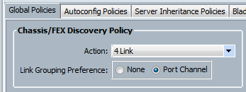
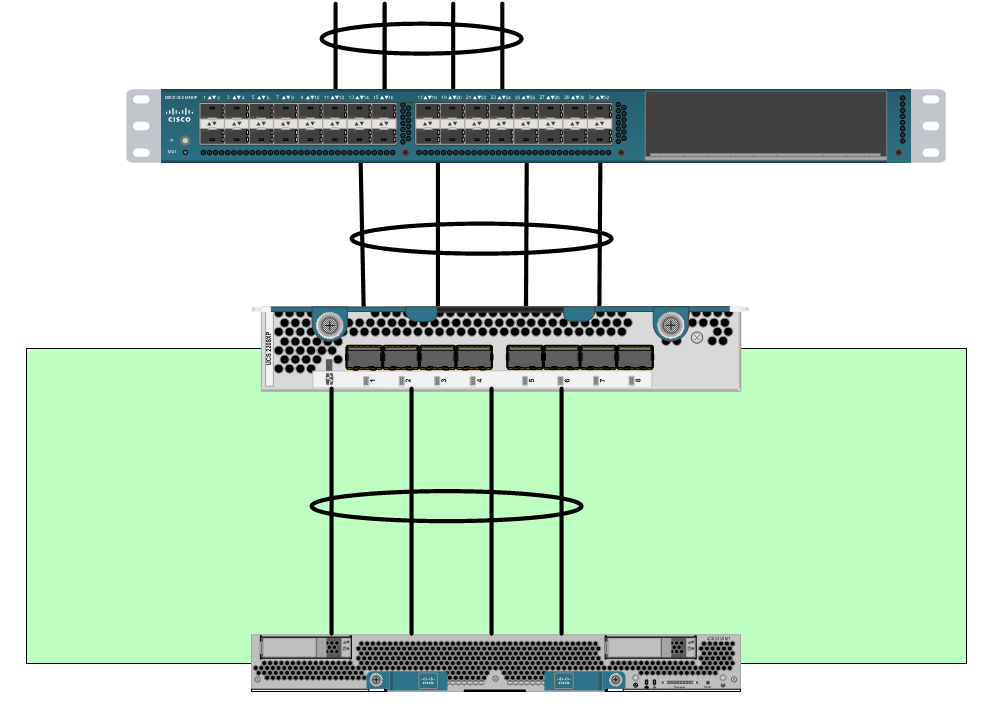
This is specifically referring to the connectivity between the Fabric Interconnects and the Chassis FEX modules or I/O modules (IOM).
You can read the Cisco documentation on this, but little explanation is given on what this actually does, and it can be a little confusing if you don’t first understand the way UCS has always bundled these links, prior to the introduction of the 22XX series IOM, which is the first to even support this functionality (also must be paired with the 62XX series fabric interconnects).
In the LAN tab of UCSM, you’ll notice an “Internal LAN” section that usually goes unnoticed:
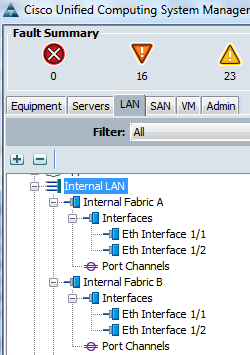
The interfaces shown are our FEX interfaces, or the ports facing the FIs from each chassis IOM.
Anyone that’s set up a UCS system can tell you that the supported connectivity is 1, 2, 4, or 8 cables to each IOM, but never 3, 5, 6, or 7. The reason for this is the way that Host Interfaces (HIF) are selected for sending traffic outbound from a UCS blade.
As I touched on in an earlier post, you can get a visual representation of the IOM ASIC by typing some simple commands. I’ll show the output for a 2104 IOM for now because it’s a bit simpler for this particular part of the post.
F340-31-16-UCS-2-B# connect iom 1
fex-1# show platform software redwood sts
Board Status Overview:
 legend:
        ' '= no-connect
        X  = Failed
        -  = Disabled
        :  = Dn
        |  = Up
        ^  = SFP+ present
        v  = Blade Present
------------------------------

        +---+----+----+----+
        |[$]| [$]| [$]| [$]|
        +---+----+----+----+
          |    |    |    |
        +-+----+----+----+-+
        | 0    1    2    3 |
        | I    I    I    I |
        | N    N    N    N |
        |                  |
        |      ASIC 0      |
        |                  |
        | H H H H H H H H  |
        | I I I I I I I I  |
        | 0 1 2 3 4 5 6 7  |
        +-+-+-+-+-+-+-+-+--+
          - | | | | : | |
         +-+-+-+-+-+-+-+-+
         |-|v|v|v|v|v|v|v|
         +-+-+-+-+-+-+-+-+
Blade:    8 7 6 5 4 3 2 1
In this IOM, there are 8 downward-facing interfaces (HIFs). This corresponds with 8 blades in a chassis, so each blade has - at most - one connection to each 2104 IOM. This is the reason why you can only get up to 20Gbit of aggregate bandwidth when using this particular model of IOM. Let’s look at the 2208 IOM:
fex-1# show platform software woodside sts
Board Status Overview:
 legend:
        '  '= no-connect
        X   = Failed
        -   = Disabled
        :   = Dn
        |   = Up
        [$] = SFP present
        [ ] = SFP not present
        [X] = SFP validation failed
------------------------------

(FINAL POSITION TBD)     Uplink #:        1  2  3  4  5  6  7  8
                      Link status:        |  |  |  |  :  :  :  :
                                        +-+--+--+--+--+--+--+--+-+
                              SFP:       [$][$][$][$][ ][ ][ ][ ]
                                        +-+--+--+--+--+--+--+--+-+
                                        | N  N  N  N  N  N  N  N |
                                        | I  I  I  I  I  I  I  I |
                                        | 0  1  2  3  4  5  6  7 |
                                        |                        |
                                        |        NI (0-7)        |
                                        +------------+-----------+
                                                     |
             +-------------------------+-------------+-------------+---------------------------+
             |                         |                           |                           |
+------------+-----------+ +-----------+------------+ +------------+-----------+ +-------------+----------+
|        HI (0-7)        | |        HI (8-15)       | |       HI (16-23)       | |        HI (24-31)      |
|                        | |                        | |                        | |                        |
| H  H  H  H  H  H  H  H | | H  H  H  H  H  H  H  H | | H  H  H  H  H  H  H  H | | H  H  H  H  H  H  H  H |
| I  I  I  I  I  I  I  I | | I  I  I  I  I  I  I  I | | I  I  I  I  I  I  I  I | | I  I  I  I  I  I  I  I |
| 0  1  2  3  4  5  6  7 | | 8  9  1  1  1  1  1  1 | | 1  1  1  1  2  2  2  2 | | 2  2  2  2  2  2  3  3 |
|                        | |       0  1  2  3  4  5 | | 6  7  8  9  0  1  2  3 | | 4  5  6  7  8  9  0  1 |
+-+--+--+--+--+--+--+--+-+ +-+--+--+--+--+--+--+--+-+ +-+--+--+--+--+--+--+--+-+ +-+--+--+--+--+--+--+--+-+
 [ ][ ][ ][ ][ ][ ][ ][ ]   [ ][ ][ ][ ][ ][ ][ ][ ]   [ ][ ][ ][ ][ ][ ][ ][ ]   [ ][ ][ ][ ][ ][ ][ ][ ]
+-+--+--+--+--+--+--+--+-+ +-+--+--+--+--+--+--+--+-+ +-+--+--+--+--+--+--+--+-+ +-+--+--+--+--+--+--+--+-+
  |  |  |  |  -  |  -  |     -  -  -  -  :  :  :  :     |  |  |  |  |  |  |  |     :  :  :  :  :  :  :  :
  3  3  3  2  2  2  2  2     2  2  2  2  2  1  1  1     1  1  1  1  1  1  1  9     8  7  6  5  4  3  2  1
  2  1  0  9  8  7  6  5     4  3  2  1  0  9  8  7     6  5  4  3  2  1  0
  ____/__/  ____/__/     ____/__/  ____/__/     ____/__/  ____/__/     ____/__/  ____/__/
    blade8      blade7         blade6      blade5         blade4      blade3         blade2      blade1
The 2208XP IOM has up to 4 connections for each blade. This gets pretty powerful when you have blades with multiple adapters (and multiple DCE interfaces per adapter, like with the VIC 1240 and VIC 1280).
See here for more info on the bandwidth capabilities for various combinations of UCS hardware.
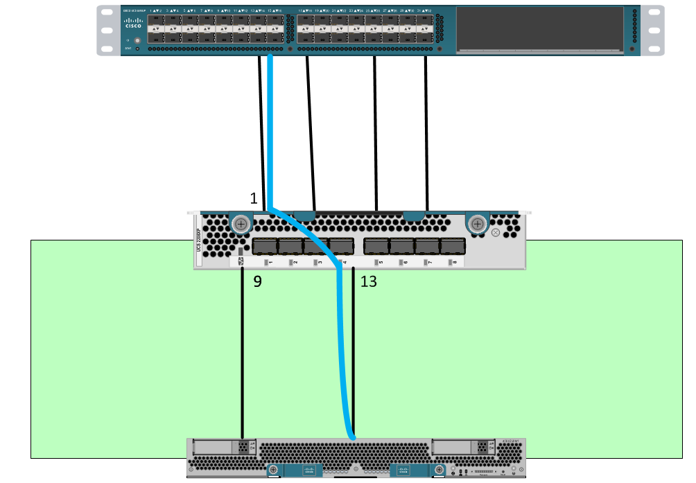
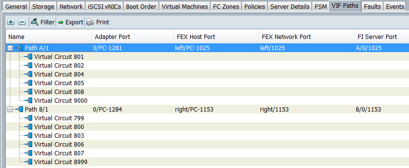
So, when we’re considering the connectivity between the blade and the IOM (and in turn the IOM and the FI), we encounter the act of “pinning” a blade’s adapter interface to a HIF on the IOM. If you go to the “VIF Paths” tab of any blade, you can see this clearly:
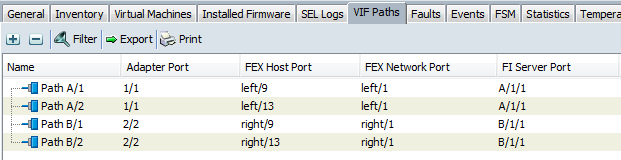
This particular blade is a B250 full-width blade, which means there are two mezzanine slots. Each slot is populated with the M81KR “Palo” adapter, so the blade itself has two connections, one per adapter, to each IOM. As you can see in the diagram above (and below), each adapter interface is pinned to a FEX Host Port, or HIF. All vNICs that are assigned to that particular path send all their traffic through that bound HIF.
In addition, each adapter is bound to a corresponding NIF, or more commonly, the FEX port. These are the ports you physically see on the back of the chassis IOM. So, what we essentially have is source-based forwarding of traffic, meaning that the age-old problem of single-link oversubscription is very possible. Example - you have one server that is VERY active (let’s say an FTP server). It’s used by all users in an organization so it sees pretty heavy use. With this configuration, you would only be able to utilize this single 10GbE link per FEX module.
This problem is extremely similar to the problem encountered when configuring the load-sharing policy for a vSwitch in VMware.
So, to rectify this, we have the ability to configure port-channels. All of what I mentioned previously regarding the “pinning” that takes place by default is quite important, because now you can realize exactly what you’re gaining by moving to this policy. First, when you connect to the NX-OS instance running on a Fabric Interconnect and show the interface status for a particular vNIC, you can clearly see that the bound interface is now a port-channel, not a specific HIF:
UCS-POD01-A(nxos)# show int veth801
Vethernet801 is up
    Bound Interface is port-channel1281
Normally it would be bound to something like “Ethernet1/1/2” where the first character is the chassis ID, and the third character is the HIF number (ignore the middle character). However, it’s bound to a port-channel, so we should take a look at that port-channel interface:
UCS-POD01-A(nxos)# show int po1281
port-channel1281 is up
.....
  Members in this channel: Eth1/1/13, Eth1/1/14, Eth1/1/15, Eth1/1/16
So now, all four HIFs that would otherwise have static bindings to each are now bundled in a port-channel. If you take a look at the load-balancing policy, you’ll realize that we’re now using an IP hash (very common and widely used for proper port channels) to determine which link to use to handle the traffic.
UCS-POD01-A(nxos)# show port-channel load-balance

Port Channel Load-Balancing Configuration:
System: source-dest-ip

Port Channel Load-Balancing Addresses Used Per-Protocol:
Non-IP: source-dest-mac
IP: source-dest-ip source-dest-mac
It’s not quite round-robin, but it’s a lot better than pinning to a single specific link.
This also applies to the links between the IOMs and the FIs. We now see port channel interfaces in our “Internal LAN” cloud:
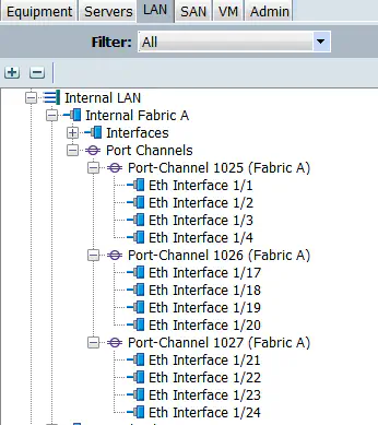
UCS-POD01-A(nxos)# show int po1025
port-channel1025 is up
...
  Members in this channel: Eth1/1, Eth1/2, Eth1/3, Eth1/4
Combine all of this with the fact that the normal uplinks from the FI to the upstream switch has functioned as a normal port channel for quite some time, and we get a much better distribution of traffic based upon the widely accepted IP hash method, and traffic is looked at on each hop along the way to determine which link to use for that particular packet.
Keep in mind that you still need to have the appropriate hardware to light up four connections to the IOM like this. To make this work, I used a B200 M3 blade with a VIC 1240 in the MLOM slot and a port expander in the mezz slot, resulting in a total of 4 DCE interfaces per fabric, so this was possible.
I hope I cleared up some of the confusion (and hopefully didn’t generate any) regarding this policy. I think it’s a great idea to enable this - just like with the standard vSwitch in VMware, if you want to be 802.3ad compliant, a policy like this is vital. The interface-pinning policy for really any technology is okay, and certainly useful if you have some bad upstream switch design. Any time you pin to an interface, you’re restricting that MAC address from leaving out any other port, so the upstream switches only learn it on that port, and therefore only send to that MAC address on that port. However, it really restricts you in the very likely event of a talkative server, or virtual machine.
For those that have been reading some of my latest posts, I have been getting really into UCS PowerTool, and the idea of automating the configuration of a UCS environment. Just wanted to mention - I’ll be enabling port-channels via this policy in every script I write.
Understanding UCS VIF Paths - UCSGuru
UCS Chassis Discovery Policy - JeffSaidSo
ASK THE EXPERTS - Cisco UCS Community