Title here
Summary here
July 1, 2013 in Systems8 minutes
This post picks up where the previous left off. Again, a CCNP-level knowledge of STP is recommended.
So…Spanning Tree didn’t converge quickly enough for some people, and enabling PortFast everywhere kind of defeats the purpose, so 802.1w Rapid Spanning Tree was born. RSTP in essence puts into place some additional features to speed up STP reconvergence. Old-school 802.1D meant that you had to wait at least 30 seconds to get a port from blocking to forwarding, and this means that recovering from a failure takes at least that much time (sometimes more depending on other factors).
The more I look at the inner workings of RSTP, the more I like it - it works much more efficiently than 802.1D and as far as STP goes, it’s alright. Truth be told, I prefer not using STP in any way, but if I have to, RSTP is not too bad - it’s a well-designed system, and I like to have it there as a safety net in case my junior engineers make cabling mistakes or if my vendor’s shiny new STP-less L2 feature fails.
RSTP speeds up convergence using a few key components:
Important note - STP is all about “which ports do I block?” You can save yourself a lot of headache by remembering that a blocked port absolutely must continue to receive BPDUs in order to stay blocked.
RSTP changes the game in a few areas. First off, RSTP uses some terms that can be very confusing. To simplify things, let’s remember that any port in a STP topology of any kind has three attributes:
RSTP has some specific stuff to keep in mind for each item in that list, so let’s take a look:
RSTP uses three Link Types. These have a lot to do with what that link is connected to (i.e. another switch vs an end host)
Point-to-Point Link - This is connected to another switch. If a switchport is operating at full duplex and is receiving Hellos, then it is a Point-to-Point Link.
Shared Link - This is connected to something like a hub. Hellos are being received but it is operating at half duplex.
Edge - This is connected to an end-device. Equivalent to PortFast in traditional 802.1d
RSTP has a few different port states compared with legacy 802.1D. Refer to the table below for comparison: here are only three port states left in RSTP that correspond to the three possible operational states. The 802.1D disabled, blocking, and listening states are merged into a unique 802.1w discarding state.
| STP (802.1D) Port State | RSTP (802.1w) Port State | Is Port Included in Active Topology? | Is Port Learning MAC Addresses? |
| Disabled | Discarding | No | No |
| Blocking | Discarding | No | No |
| Listening | Discarding | Yes | No |
| Learning | Learning | Yes | Yes |
| Forwarding | Forwarding | Yes | Yes |
Note that Listening is not a port state included in RSTP - it goes right from discarding to learning.
Port roles determine what part a port is playing in the overall spanning tree topology. RSTP uses the same port roles as traditional STP, with a few additions:
Root Port - Same as 802.1d Root Port; represents the best cost port to use to get to the root
Designated Port - Same as 802.1d Designated Port; a port that is neither an RP or in a blocking/discarding state. From a segment/collision domain perspective, this port is the best option to get to the root bridge
Alternate Port - Same as the alternate port concept when using UplinkFast in 802.1D; serves as an alternate path to the root to be unblocked quickly upon a topology change. These ports are blocked because they received more useful BPDUs from another bridge, but were not chosen to be the root port.
Backup Port - a port that can quickly move to be a Designated Port if the primary DP goes down. It is blocked because it received a BPDU that it’s own switch was advertising - therefore this is only valid in shared LAN environments (i.e. half-duplex hubs)
So, in short, there are two ways to be a blocked port in RSTP - Alternate and Backup. Since shared LANs are all but extinct now, you almost always see blocked ports in the “Alternate” role. A backup port would indicate that the same bridge was connected more than once to the same shared media. (There’s a third state called Designated Blocking - see the section labeled RSTP Synchronization for more on this)
RSTP uses the same BPDU length to ensure some level of compatibility with switches that are running 802.1D. Traditional STP BPDUs are actually pretty simple. Beyond advertising information about the root bridge, they didn’t do much else. See that the “version identifier” is set to 0 to indicate STP:
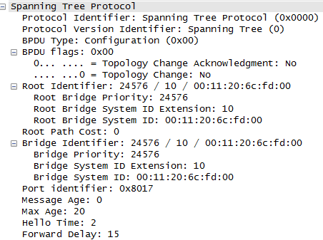
You’ve got some information in there about Topology Change bits but that’s about it. However, if you look at “BPDU flags” you’ll notice that only two bits are used for BPDU flags, and a whole byte was allocated for flags.
RSTP actually makes use of these additional flag bits:
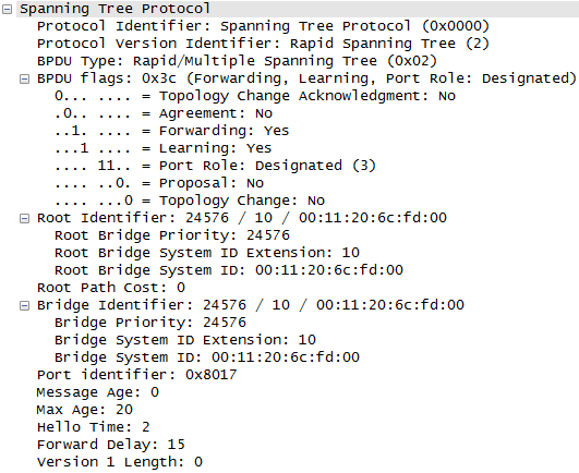
In addition to the familiar topology change bits, we can now specify if this BPDU is part of an RSTP Synchronization handshake (more on this later), the port role that this was sent on, and more.
By the way, if an RSTP-enabled switchport receives an 802.1D BPDU, it will revert back to traditional STP mode and will follow all of the old 802.1D rules, including the 15 second forward delay.
I think it’s cool that wireshark identifies this BPDU’s version (0x02) as being “Rapid/Multiple Spanning Tree” which reminds me that MST uses RSTP on the back-end, not old 802.1D.
In RSTP, the only time a “topology change” is recognized is what a non-edge port moves to the forwarding state. This is a big difference from 802.1D, since link-down events no longer immediately cause a TCN. In addition, because of the fact that BPDUs are sent by every bridge, this means that we don’t have to send a TCN BPDU to the root bridge, we can instead send BPDUs directly from the bridge that encountered the failure.
When a RSTP switch detects a topology change, it:
Starts a TC While timer set to twice the hello-time for all non-edge ports (and RP if needed). While this timer is active, BPDUs are also sent out of the root port, and all BPDUs have the TC bit set.
Flushes all MAC addresses associated with these ports
If there’s one functional aspect that really sets RSTP apart from traditional 802.1D, it’s the proactive nature of RSTP, whereas STP was more or less passive.
For instance - in RSTP, BPDUs are sent by all bridges, and are used as a method of detecting immediately adjacent STP failures. BPDUs are used as a form of heartbeat between two RSTP “neighbors”, rather than only the root bridge sending it out. In 802.1D, a loss of BPDUs on a root port did not necessary mean it was the next switch up the tree that failed - it could have been any switch up the line to the root bridge, including the root bridge itself.
RSTP synchronization requires a little more of an interactive demonstration in order to explain properly and succinctly - to that end, I give you a new KIC LAB covering this specific topic:
The idea of detecting indirect links is not new, but in traditional STP, this was a Cisco-proprietary function achieved through RLQs, or root-link queries. With RSTP, it is now a function of the fact that all bridges keep heartbeats with each other, since all bridges send BPDUs, not just forward the root’s BPDUs.
Let’s take a look at our three-bridge topology. SW1 is the root, and the link between SW1 and SW2 fails. SW3 receives a BPDU from SW2 advertising itself as the root bridge. Since SW3 knows that the correct root bridge, SW1 is still alive and well, SW3 is able to inform SW2 that it’s not the root, and that the root bridge is now accessible to SW2 through SW3, instead of a direct connection.
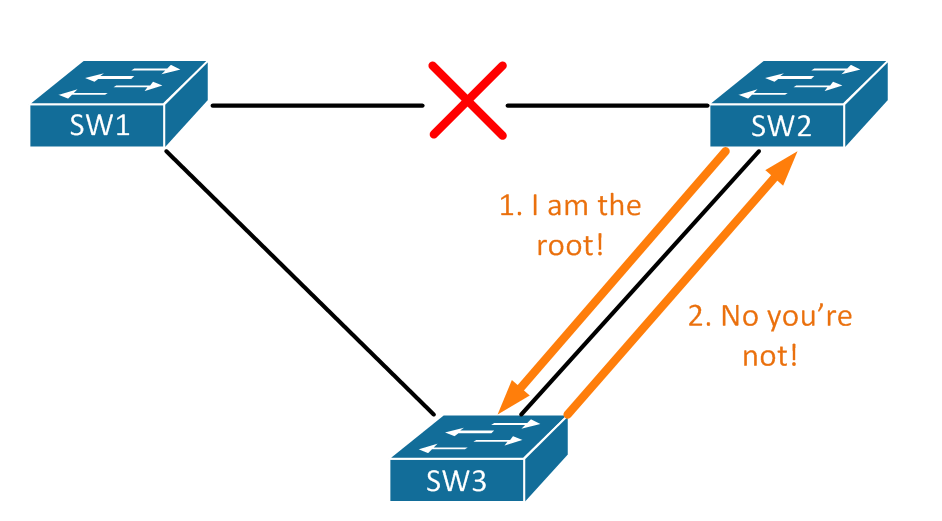
This means that SW3 is actually able to accept inferior BPDUs on it’s previously blocked ports. Remember, superior BPDUs are required to be constantly received on a blocked port for it to stay blocked. Since SW2 should not be the root, SW3 sees the new BPDUs come into the blocked port connected to SW2, see that it’s inferior, and inform SW2 that a true root port is available through SW3. Through this, SW2 moves it’s connection to SW3 from the designated to the root port role, and stops sending its own BPDUs.
The concept of UplinkFast in old-school 802.1D STP was that we could quickly reconverge on a new root port if our existing root port goes down. It did this by remembering which ports are viable root ports, even if they were bested by another port on the switch because of cost, etc. So, if the existing root port goes down, the new root port can be brought up much more quickly than the normal way of going through the 30 seconds of listening and learning before we’re able to forward again.
The behavior of UplinkFast, specifically the function of remembering alternative root ports, is baked into the RSTP standard, manifested in the “Alternate” port role.
This is the go-to document from Cisco on RSTP - http://www.cisco.com/en/US/tech/tk389/tk621/technologies_white_paper09186a0080094cfa.shtml